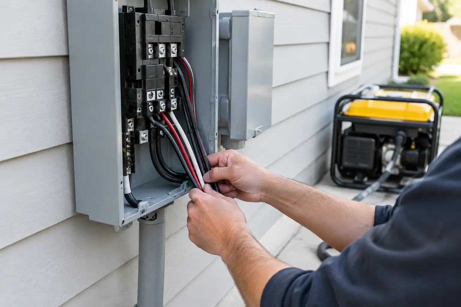
Generator inlet box wiring is the connection between a portable generator and a home’s transfer equipment. A properly installed inlet provides a weather-resistant connection for the generator cord, while a transfer switch or listed panel interlock prevents the generator from energizing the utility supply.
An incorrect installation can create shock, fire, equipment-damage, or utility-backfeed hazards. For that reason, the inlet, wiring, transfer equipment, overcurrent protection, grounding and bonding arrangement should be treated as one electrical system rather than as separate accessories.
For most homeowners, this is not a do-it-yourself wiring project. A qualified electrician should install and test the inlet box, transfer equipment, conductors, grounding and bonding arrangement, and overcurrent protection according to the equipment manufacturer’s instructions and applicable local electrical requirements.
You can still prepare for the installation by understanding how the inlet, generator cord, transfer equipment, circuit protection, and generator output work together.
What an Inlet Box Does in a Generator Setup
A generator inlet box is a wall-mounted or recessed electrical inlet that provides a connection point for a portable generator. Residential models are commonly installed outdoors and are designed to connect the generator cord to wiring that leads to transfer equipment or a listed panel interlock.
The inlet box is not a transfer switch and does not by itself prevent utility and generator power from being connected at the same time. That isolation is provided by an approved transfer switch or a listed panel interlock designed for the specific electrical panel.
That distinction matters. Never connect a portable generator to a home’s electrical system through a dryer receptacle, range receptacle, or a male-to-male cord. These methods can bypass the protection provided by properly installed transfer equipment and create dangerous backfeed onto utility lines. The U.S. Consumer Product Safety Commission has specifically warned consumers not to use male-to-male extension cords because their exposed prongs can create electrocution and fire hazards.
A properly planned setup typically includes the generator, a compatible generator cord, an outdoor inlet box, a listed transfer switch or panel interlock, suitable conductors and conduit where required, and overcurrent protection appropriate for the equipment and installation. If you are powering a well pump, refrigerator, furnace blower, sump pump, or other essential circuits, every part of that chain needs to support the intended electrical load.
Inlet Box Wiring Starts With the Right Rating
The generator outlet, cord, inlet box, transfer equipment, conductors, and overcurrent protection must be compatible with the system’s voltage and current ratings. The generator’s actual rated output also matters: an inlet with a higher amp rating does not increase how much power the generator can produce.
A 30-amp setup is common for portable generators that provide a 120/240-volt L14-30 connection. The theoretical power calculation at 240 volts is 7,200 watts, although specific inlet boxes and generator systems may be marketed with different maximum-wattage specifications. Always follow the ratings of the actual generator, inlet, cord, transfer equipment, and overcurrent protection rather than relying on the wattage calculation alone.
A 50-amp setup may be used with larger portable generators that provide a compatible 120/240-volt 50-amp connection. Depending on the generator and inlet, the connection may use a locking or straight-blade configuration. The exact connector must match the generator outlet, cord, inlet, and transfer equipment.
At 120/240 volts, 50 amps corresponds to a theoretical 12,000 watts when both legs are fully utilized. That does not mean the generator can actually produce 12,000 watts. Its continuous and surge ratings remain the practical limits of the system.
Do not use a higher-rated inlet as a way to increase generator capacity. The system must be designed around the generator’s output and the ratings of the inlet, cord, conductors, overcurrent protection, and transfer equipment. The electrician should verify that the complete installation is compatible rather than sizing one component in isolation.
For an outdoor installation, choose an inlet box listed for the intended location and equipped with a cover designed to protect the connection from weather and contamination. Look for clear ratings, durable construction, secure terminals, and installation instructions that match the intended wiring method.
Common residential inlet boxes are available in several amperage and connector configurations. The specific model should be selected according to the generator outlet, cord configuration, transfer equipment, enclosure rating, and installation requirements.
Match the Cord to the Inlet and Generator
Your generator cord must have the correct connector for the generator on one end and the matching inlet connection on the other. The cord should also be rated for the voltage, amperage, outdoor environment, and intended use of the generator system.
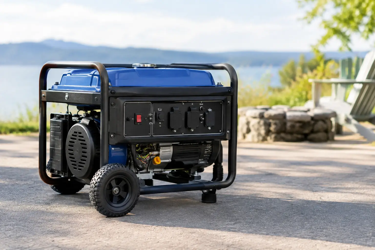
The cord should be long enough to allow the generator to remain in a safe outdoor operating location. The CPSC recommends operating portable generators outdoors at least 20 feet from homes and buildings, with exhaust directed away from windows, doors, and vents. Never operate a portable generator inside a home, garage, basement, crawlspace, shed, or other enclosed area, even if doors or windows are open.
Do not substitute an ordinary household extension cord for a generator cord. Use a purpose-built generator cord with the correct connector configuration, conductor size, voltage and amp rating for the equipment. Inspect the cord before use for cracked insulation, damaged connectors, bent blades, heat damage, or corrosion.
A heavy-gauge generator cord with the correct connector configuration is designed specifically for this type of application.
===> Check Generator Inlet Box Options
What Happens Behind the Inlet Box
In a common 120/240-volt residential installation, the inlet connection uses conductors for the two ungrounded conductors, the grounded conductor (neutral), and the equipment grounding conductor. From the inlet, the wiring connects to the transfer equipment or other approved equipment according to the installation design.
Conductor size, wiring method, conduit requirements, overcurrent protection, and terminal connections depend on the equipment ratings, installation method, conductor length, environmental conditions, and applicable electrical requirements. These details should be verified against the manufacturer’s instructions and the requirements governing the installation.
This is where generic generator inlet wiring diagrams can become misleading. A diagram showing black, red, white, and green conductors does not establish the correct wiring method for every installation. It cannot account for the specific transfer switch, panel, generator neutral configuration, conductor requirements, conduit, overcurrent protection, or local electrical requirements. A wiring diagram should therefore be treated as equipment-specific information, not as a universal installation guide.
The electrician also needs to determine whether the generator has a bonded neutral and how the transfer equipment handles the neutral conductor. Portable generators can use different configurations, and the correct arrangement depends on the generator, transfer equipment, and electrical system. An incorrect neutral-to-ground connection can create objectionable current paths or interfere with the intended operation of protective devices. Do not remove a factory bonding connection or add a bonding plug unless the generator manufacturer and the transfer-equipment instructions specifically call for that configuration.
Grounding requirements also depend on how the generator is connected and used. A portable generator supplying cord-and-plug-connected equipment directly can have different grounding requirements from a generator connected to a building through transfer equipment. Do not assume that a ground rod is either always required or never required. The generator manual, transfer-equipment instructions, applicable electrical requirements, and the electrician’s assessment should determine the grounding arrangement for the installation.
Transfer Switch vs. Panel Interlock for Generator Backup
A manual transfer switch can provide a defined group of emergency circuits. The electrician moves selected circuits, such as the refrigerator, lighting, networking equipment, furnace, garage door opener, or sump pump, onto the transfer switch. During an outage, the homeowner follows the manufacturer’s operating sequence: place the generator in its approved outdoor location, connect the generator cord, start the generator as instructed, and operate the transfer equipment according to its instructions.
A panel interlock works differently. It mechanically prevents the utility main and generator breaker from being operated in an incompatible position at the same time. The interlock must be listed or approved for the specific panel and installed according to its instructions; an improvised bracket or generic hardware is not an acceptable substitute.
The two approaches serve different installation goals. A manual transfer switch can provide a defined group of emergency circuits, while a listed panel interlock can allow the homeowner to select circuits from the main panel subject to the generator’s capacity and the installation’s limitations. The appropriate configuration depends on the electrical panel, generator output, desired loads, equipment compatibility, and applicable requirements.
Plan Loads Before You Size the Inlet
An inlet box is part of a power system, not a standalone purchase. Start with the loads you actually need during an outage. Refrigerators, freezers, lighting, networking equipment, phone chargers, and gas-furnace blowers may fit within a modest generator’s capacity, but their actual running and starting requirements should be checked before combining them on one generator.
Electric water heaters, heat pumps, central air-conditioning systems, electric ranges, clothes dryers, and large shop tools can consume substantial power and may require significant starting capacity. Do not assume that a generator can support these loads simply because its headline wattage appears high enough.
Motors deserve special attention because starting demand can be substantially higher than running demand. A sump pump, well pump, refrigerator compressor, or RV air conditioner may have a running wattage that looks reasonable but a much higher starting demand. A 240-volt well pump also affects the installation because it requires a generator and inlet configuration capable of supplying both hot legs at the required voltage.
Write down each essential load, its running watts, and its starting watts where applicable. Compare the combined loads with the generator’s rated running output and its available starting capacity. Leave operating margin rather than planning to run continuously at the generator’s maximum rating, and follow any load-management limits in the generator and transfer-equipment manuals.
This approach is also useful for small jobsite setups, where a generator may need to support battery chargers, lights, a circular saw, and occasional pump use without exceeding its available capacity.
Questions to Ask Before Installation
Before an electrician arrives, have the generator model, outlet types, running watts, peak watts, and the list of circuits you want to support. Also ask whether a 30-amp or 50-amp generator connection is appropriate for your equipment, whether your panel is compatible with a listed interlock, and whether a transfer switch would provide a simpler way to manage essential circuits.
Also ask where the inlet box will be mounted and where the generator will operate. The generator must remain outdoors and in a location that follows the manufacturer’s instructions and CPSC carbon-monoxide guidance. CPSC recommends keeping portable generators at least 20 feet from homes and buildings, with exhaust directed away from windows, doors, and vents. The inlet location should not encourage placement of the generator closer to the building simply because the cord run is shorter.
After installation, request a clear demonstration of the exact operating sequence for your equipment. Make sure everyone who may operate the system understands where the generator should be placed, how the cord is connected, how the transfer switch or interlock is operated, which loads can be used together, and how the system is shut down. Practice the procedure in daylight before an outage occurs.
A professionally installed generator inlet box is only one part of a safe backup-power system. The generator, cord, inlet, wiring, transfer equipment, overcurrent protection, grounding and bonding arrangement all need to work together. The most useful setup is one that matches the generator’s actual capacity, prevents utility backfeed through approved transfer equipment, keeps the generator safely outdoors, and is simple for everyone in the household to operate correctly when the power goes out.